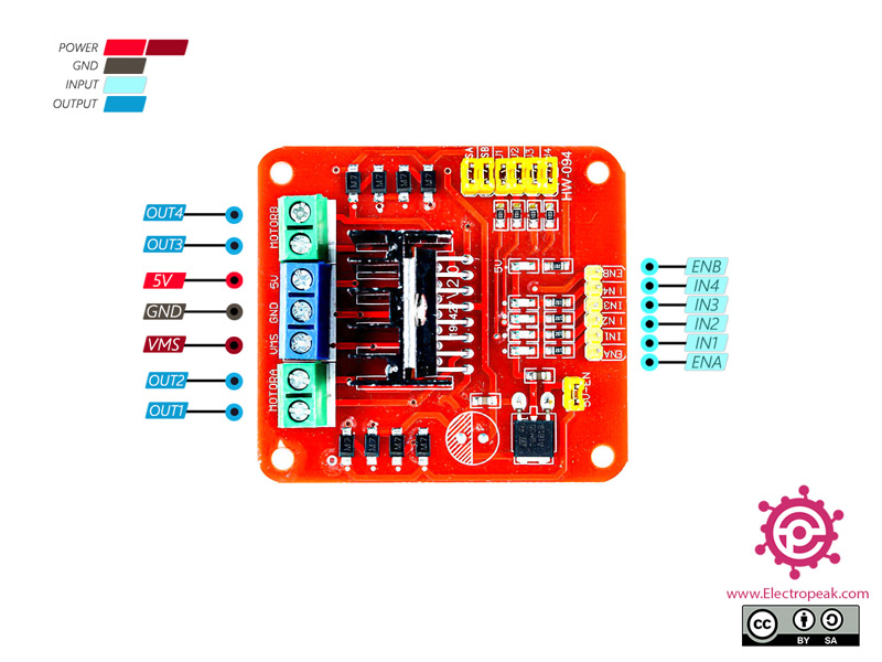

These instructions are based on the silkscreen of the board that I have.
#L298n motor driver connection with arduino how to#
I'll provide a quick demo program so you can see how to run the motors through a predefined sequence. In the second part I will show you how to quickly wire up the driver to an Arduino. It should also give you ideas for very simple robot projects. This will give you a better understanding of how a motor driver works. In the first part I will show you how to control the driver without the need for a computer. Most motorized toys and many robot chassis kits use simple DC motors.

In this way, we can control the direction of rotation of motors.In this tutorial I cover how to drive two DC (direct current) motors using an L298N motor driver. If both the terminals are given as either LOW or HIGH then we can see that there is no potential difference between the terminals therefore the motors won’t run. If the voltage at terminals is interchanged means HIGH in above is made LOW and LOW is made HIGH then the direction of the motors is reversed. One pin of the motor will be in higher potential and others will be in lower potential. Using two digital pins with one as HIGH and one as LOW we are creating a potential difference between the terminals of the motor.

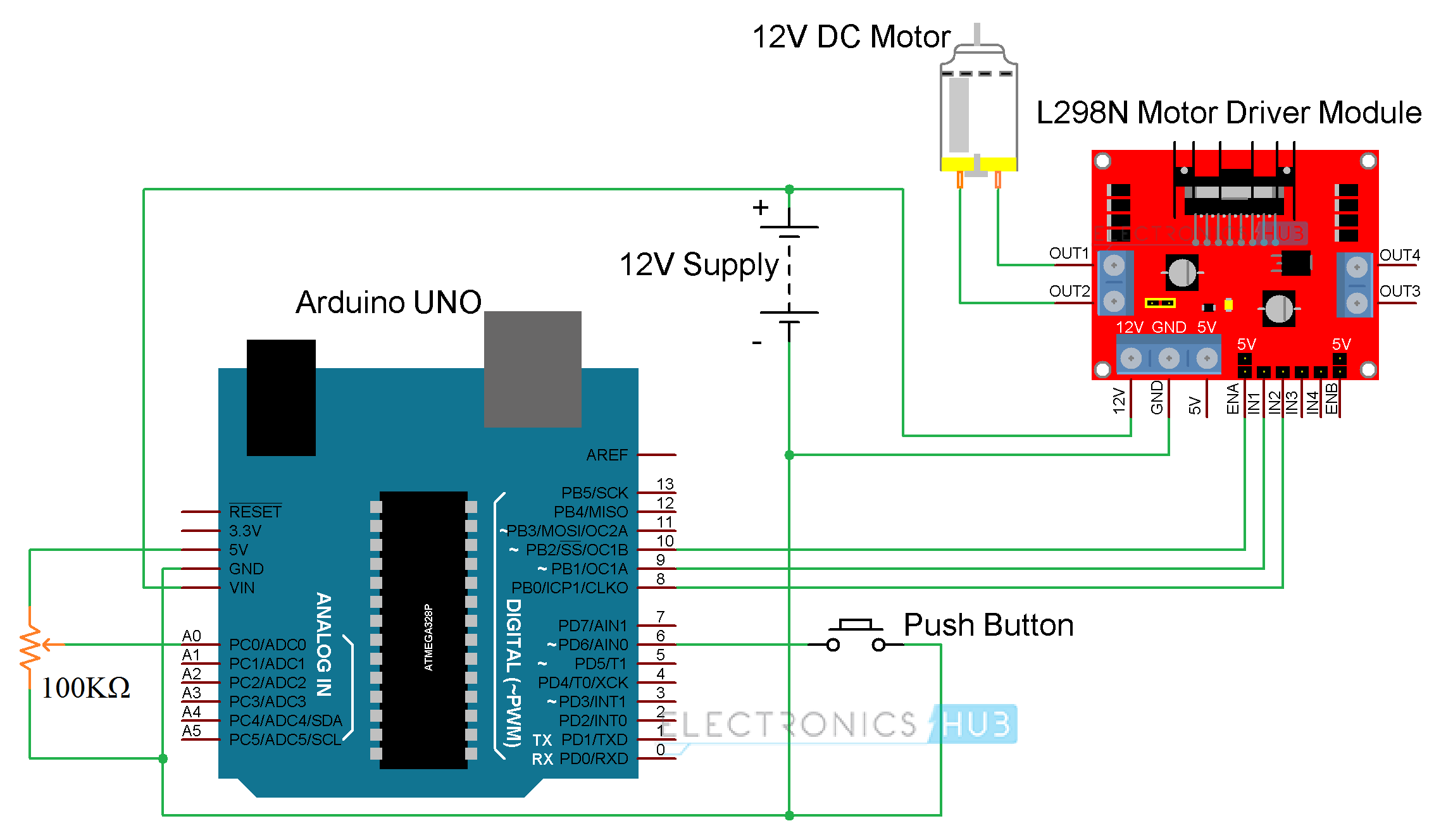
We know that we can program output voltages in Arduino. This potential difference is created and controlled by the Arduino (microcontroller unit). WORKING EXPLANATION OF L298N Generally, a motor works when there is a potential difference between two of its terminals. See that the ground pin and 12V pin do not touch each other as it will lead to the failure of the battery and L298N module.See that connections are made properly and be careful with the terminals of the battery.The four output pins of the motor driver are connected to the terminals of the motor.


 0 kommentar(er)
